

+aeb Vacuum Diagram Audi A4 B5 1.8t
Audi A4, A6, A8 – 1997 to 2000 – two.4, 2.vi, two.8 – Petrol Engines – Scheduled Plan
Oct 10, 2018 in Audi A4 B5 (1994 to 2001), Audi A6 C5 (1997 to 2005), Audi A8 D2 (1994 to 2002), Scheduled Service / Maintenance Plans past admin
All y'all need to know to service your Audi A4 B5, A6 C5 and A8 D2 (years 1997 to 2000) with petrol engines, according to the Official Audi Service Schedule Interval Plan / Scheduled Maintence Servicing.
All the information in this article is in accord with the Service Schedule Intervals Plan specified by Audi. Nevertheless, you should allways ostend with your car owners manual before any servicing.
Every one yr or 12.000 kms / 7.500 miles schedule service interval:
- Change engine oil and oil filter
- Check Fluid Levels
- Clean Plenum H2o Valve
- Check Automobile-Shift Lock
- Reset the service reminder
- Manual transmission – check shift and clutch interlock
Additionally every 24.000 km / 15.000 miles schedule service interval:
- Check Battery level
- Replace Dust/Pollen Filter
- Checking and adjusting the level Cooling System
- Checking and adjusting Wiper & Washer System
- Gearbox, power railroad train, drive shafts – check for oil leaks and play – In event of leakage from the gearbox, bank check the gearbox oil level
- Clean and lube rails of Sliding Roof
- Check lubricant on Transmission Final Drive(s)
- Bank check Restriction System
- Bank check DTC retentiveness – OBD
- Outside lights: Cheque all lights and supplant if needed
Additionally every 48.000 km / 30.000 miles schedule service interval:
- Replace the engine Air filter cleaner (ACL) and clean the engine air filter housing
- Replace the Engine Spark Plugs
- Replace the Brake Oil fluid
- Modify Oil Haldex clutch, only Audi TT Quattro
- Replace Spark Plugs
This maintenance programme is suitable for the following model years:
– 1996, 1997, 1998, 1999 and 2000 – Audi A4 B5 Petrol Engines (2.4, ii.6 and 2.8)
– 1996, 1997, 1998, 1999 and 2000 Audi A6 C5 Petrol Engines (2.4, two.6 and two.eight)
– 1996, 1997, 1998, 1999 and 2000 Audi A8 D2 Petrol Engines (2.4, 2.6 and ii.8)
Audi B5 S4 RS4 (1997 – 2001) – How to Remove the Engine
Baronial 28, 2016 in Audi A4, Audi A4 B5 (1994 to 2001) by admin
How to Remove Engine Audi S4 RS4 B5
Annotation:
- All cable ties opened or cut during engine removal must be reinstalled at the aforementioned locations.
- Remove engine without transmission toward the front.
- Drained coolant must be stored in a make clean container for disposal or reuse.
- Always replace seals and gaskets.
- Do not open coolant circulation system.
Removing
– Outset make up one's mind whether a coded radio is installed. If so, determine the correct coding.
– Switch ignition off and disconnect battery Basis (GND) strap.
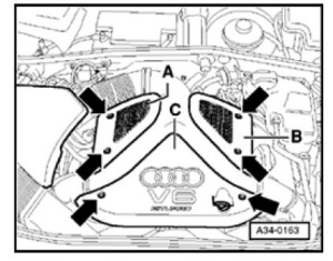
– Remove bolts (arrows) and remove engine covers -A- and -B-.
– Remove encompass in a higher place air filter.
– Remove plenum cover.
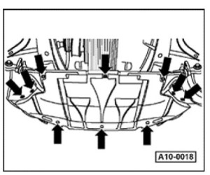
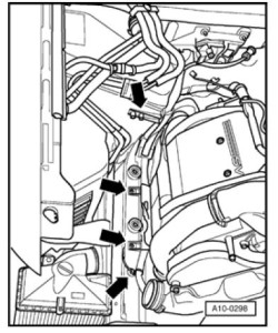
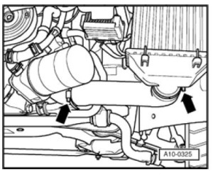
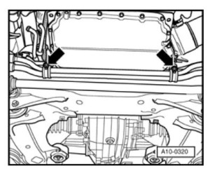
– Remove sound-proofing cloth (arrows).
– Remove bracket for sound-proofing at unit support.
– Bleed engine coolant => folio 19-19
– Remove front bumper:
=> Repair Manual, Body Exterior, Repair Group 63
– Remove lock carrier:
=> Repair Manual, Body Exterior, Repair Grouping l
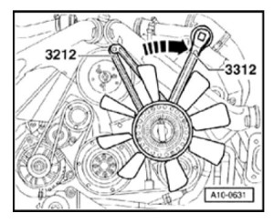
– Remove pasty fan counter-concur using 3212 spanner wrench.
Note:
- The mucilaginous fan has a left-handed thread.
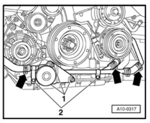
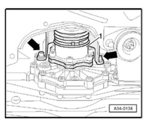
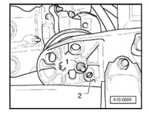
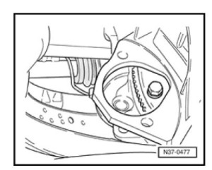
– Mark direction of rotation of ribbed chugalug
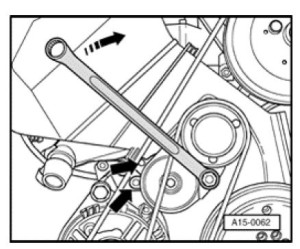
– To loosen ribbed belt, plough clockwise using 17 mm box wrench until two holes are
aligned (arrow). Counter-hold in position using 3204 drift.
Note:
- Mark direction of rotation of ribbed belt. Reversing the direction in which it runs tin ruin it.
– Remove ribbed belt.
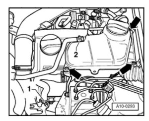
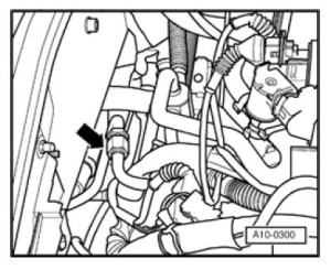
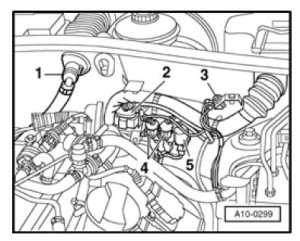
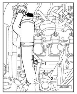
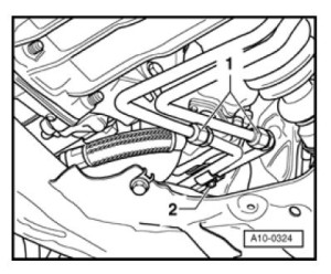
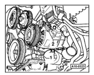
– Cut coolant hoses -one- and -2-
– Remove coolant reservoir (arrows).
– Disconnect connector for coolant level display.
– Remove valve cover (cylinder banking concern 4-6).
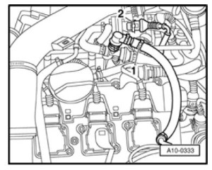
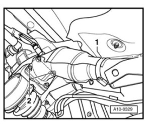
– Remove hose -1- to vacuum reservoir.
– Remove air benefactor (arrows).
WARNING!
Fuel arrangement is nether pressure! Before opening the organisation place a rag
around the connection. Then release pressure by carefully loosening the
connection.
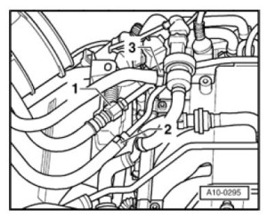
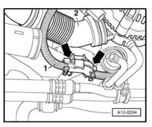
– Disconnect fuel supply and return lines -ane- and -2- and movement aside.
– Remove hose from Evaporative Emission (EVAP) canister purge regulator valve -iii-.
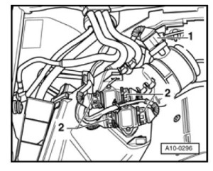
– Disconnect connector -i- at Mass Air Catamenia (MAF) sensor.
– Disconnect connectors -2- from power output stage and lay cables aside.
– Remove air filter.
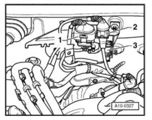
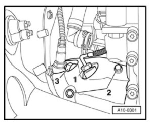
– Disconnect connector -1- for oxygen sensor at bulkhead.
– Disconnect connector -2- for knock sensor.
– Disconnect harness connector -3- and movement cables clear.
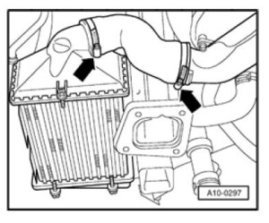
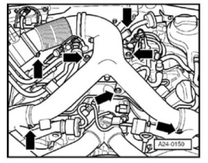
– Remove pressure hoses (arrows) from charge air cooler to left and correct pressure lines.
– Disconnect cable at B+ on battery.
– Disconnect B+ battery cable.
– Move aside cables to starter together with cable channels (arrows).
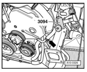
– Disconnect hose from power steering reservoir to power steering pump with special tool 3094.
– Disconnect power steering hose (arrow).
– Disconnect hydraulic line (pointer).
– Disconnect harness connector from vehicle speed sensor.
– Disconnect harness connector from reverse gear switch.
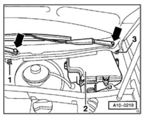
– Remove wiper arms (arrows).
– Disconnect retaining clip -one- at water deflector.
– Pull off left and right retaining clips -3- on water deflector.
– Remove h2o deflector.
– Remove cover -2- from E-box (electronics box).
– Open East-box in plenum.
– Unclip ECM retaining subclass.
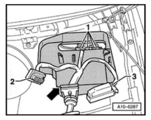
– Remove ECM, disconnect harness connectors -2- and -3- and remove.
– Disconnect harness connectors -1-.
– Remove hose -ane- to power restriction booster at bulkhead.
– Disconnect basis (GND) -three-.
– Disconnect connectors -2- and -5- at bulkhead and remove lower role of connectors
from bracket.
– Pull connector -4- out of subclass and motility wiring clear.
– Remove bracket for harness connector.
– Remove both coolant hoses to rut exchanger at engine by un-clipping retaining clips on flange.
– Remove hoses (arrows) from turbocharger to left and right charge air coolers.
– Move aside cable -1- to starter by cutting cable necktie and un-clipping subclass (pointer).
– Remove hose -2- for cooling generator.
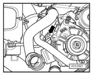
– Disconnect ground (GND) (arrow) from engine support.
– Remove hose clamp (pointer).
– Remove intake manifold -1-.
– Remove coolant line -2-.
– Remove torque support -1-.
– Remove hose clamps (arrows).
– Remove coolant line -2-.
– Identify VAG 1306 Baste Tray beneath engine.
– Remove oil filter.
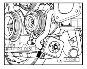
– Remove hose clamps (pointer).
– Remove oil cooler -ane-.
– Remove estrus sensor -ane- from right turbocharger using 3035.
– Remove heat shields -2- from left and right turbochargers.
– Remove upper bolts -3- to front line to left and correct turbochargers.
– Remove heat shield (arrows) above left and right drive axle to transmission.
– Remove hose clamp -1- from left and right heat shield for turbocharger.
– Unbolt left and right frazzle pipes -2- from turbocharger.
– Unbolt coolant lines to oil pan (arrows).
– Disconnect transmission fluid lines -1-.
– Disconnect oil line at turbocharger -2-.
CAUTION!
Do non open the refrigerant circuit of the Ac system.
– Remove A/C compressor -one…2-.
– Attach A/C compressor (with refrigerant hoses fastened) to vehicle using wire.
Note:
- When installing pay attending to guide bushings.
- When installing offset insert commodities -one- in A/C compressor.
- Do not bend or stretch lines or hoses as condenser and/or refrigerant lines/hoses may be damaged.
– Marking installation positions for threaded assemblies -one- and positioning sleeves -2-.
– Remove nuts -ane- on left and right engine mounts.
Annotation:
- When installing, make certain that locating sleeves -2- engage again.
Vehicles with automatic transmission:
– Remove right charge air cooler by disconnecting upper hose connectedness; charge air
cooler supported in 3x prophylactic bearings.
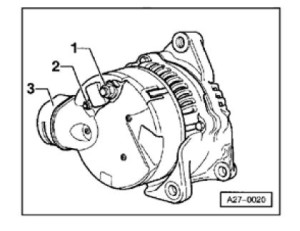
– Disconnect air guide at generator back up -3-.
– Unbolt cable at terminal 30/B+ -1-. Tightening torque: 16 Nm
– Unbolt cable at final D+ -2-. Tightening torque: iv Nm
– Remove hex socket commodities -1-, retaining nut -2-. Tightening torque: 45 Nm
– Remove bolt -iii-. Tightening torque: 22 Nm
– Remove generator -4- downward and out.
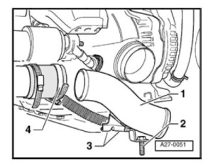
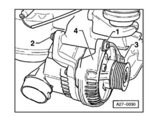
one – Remove air intake -1-.
two – Securing points for oil and A/C lines
iii – Securing point to engine block
4 – Remove hose clamp
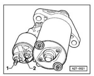
– Unbolt cablevision for terminal thirty/B+ -1-. Tightening torque: 16 Nm
– Disconnect connector for terminal fifty -2-.
– Remove right wheel.
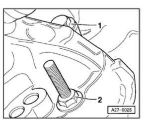
– Remove upper bolt -1- through right wheel housing. Tightening torque: 65 Nm
– Unbolt lower bolt from engine side. Tightening torque: 65 Nm
– Remove starter forrad and out.
– Using special tool V175 disconnect torque converter from drive plate.
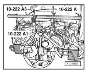
All models
– Position 10-222A engine back up bridge on bolted flanges of fenders.

– Using 10-222 engine sling together with ten-222A1 engine support bridge and 10-222A3 lift engine upward.
– Remove flange bolts from below.
– Remove engine support.
– Remove flange bolts from above.
– Attach 2024A engine sling at right-rear and left-front and secure.
Notation:
- To properly balance assembly, mounting hooks must be inserted in rails as shown in illustration.
WARNING!
Install mounting hooks and pins on the engine sling and secure them with
the positioning lock.
– Remove front end left wheel.
– Support transmission using floor jack.
– Button engine crane into position and attach to engine sling.
Note:
- Verify that all hoses and lines between engine and transmission have been
disconnected.
– Carefully pull engine out toward front end until costless.
– Guide engine forward out of engine compartment.
– Remove spacer between engine and manual.
Engine, attaching to engine stand up
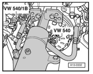
For engine disassembly and associates, mountain engine to an assembly stand using VW
540 Holding Fixture together with VW 540/1B auxiliary pieces.
Installing
Installation is reverse of removal, noting the following:
Notation:
- Always replace cocky-locking basics, bolts equally well as gaskets and O-rings.
– Install clutch
=> Repair Transmission, 6 Spd. Manual Manual 01E, Repair Grouping 30-Make certain centering sleeves for engine to manual are correctly installed in cylinder cake. Install or replace if necessary.
– Lubricate splines on transmission input shaft lightly using sparse blanket of Thou 000 100. Do not lubricate guide sleeve for release begetting.
– Check centering of clutch disc.
– A pilot needle bearing must be installed in the crankshaft in engines for vehicles with transmission manual. Install if necessary => page 13-35.
– Install spacer between engine and manual.
– Install ribbed belt => page 13-1.
– Fill up coolant => page 19-19.
– Check manual fluid level in manual manual
=> Repair Manual, 6 Spd. Manual Transmission 01E, Repair Grouping 34
Annotation:
- But reuse drained coolant if cylinder head or engine block was not replaced.
- Dirty coolant must not be reused.
– Install engine mounts without tension or preload by aligning engine with shaking
motions earlier tightening engine mounts.
– Install lock carrier with attachments.
=> Repair Transmission, Torso Outside, Repair Grouping fifty
– Install exhaust system free of stress.
– Adhere vacuum lines => page x-28
– Only remove and install spark plugs using 3122B spark plug removal tool.
– For harness connectors and routing:
=> Electrical Wiring Diagrams, Troubleshooting & Component Locations
Later connecting battery, enter anti-theft lawmaking for radio.
=> Radio operating manual
– Fully close front ability windows to finish.
– And then activate all power window switches ("upwardly") for at least ane second to activate
automatic window raising/lowering.
– Fix clock to correct time.
– Cheque engine oil level before starting engine.
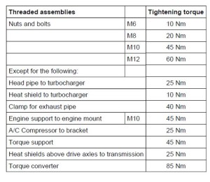
Tightening torques
Notation:
- Tightening torques are valid only for nuts and bolts that are lightly greased, oiled, covered with a thin coat of phosphate or blackened.
- Additional lubricants such as engine or transmission oil may exist used equally long as they do not contain graphite.
- Do not use whatsoever degreased parts.
- Permissible deviations for tightening torques " fifteen%.
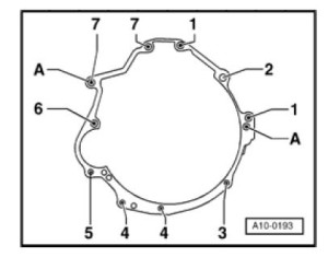
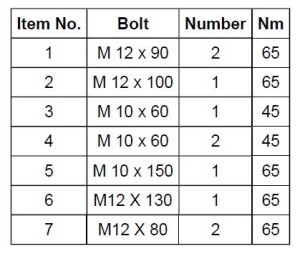
Manual to engine (6-cylinder)
-A- Centering sleeves
The instructions in this tutorial will work in the following model years:
– 1997, 1998, 1999, 2000, 2001 Audi A4 S4, RS4
Audi A4 B5 (1995-1998) Wiring Diagrams
Baronial 26, 2016 in Audi A4, Audi A4 B5 (1994 to 2001) by admin
Certificate Index
Diagram 1 – Starting and Charging
Diagram 2 – M3.two Motronic Fuel Injection Arrangement (1.6 and ane.8 models)
Diagram iii – Simos Fuel Injection Organisation (i.6 models)
Diagram 4 – 1.ix Diesel Direct Injection System
Diagram 5 – Automated Gearbox (four-speed)
Diagram half dozen – Brake and Reversing Lights, Headlight Range Control, Headlights, Rear Lights, Glove Box Light
Diagram vii – Foglights, Plow Signal Lights, Chance Warning Lights
Diagram 8 – Interior Lighting, Dual Tone Horn, Fresh Air Blower and Heated Rear Window, Cigarette Lighter
Diagram 9 – Windscreen Wash/Wipe, Headlight Launder, Outside Mirrors – Heated and Adjustable With Retractable Role
Diagram 10 – Electrical Windows, Anti-lock Braking Organization (Front Wheel Drive)
Diagram 11 – Fundamental Locking
Diagram 12 – Musical instrument Panel
The instructions in this tutorial will work in the following model years:
– 1995, 1996, 1997, 1998 Audi A4 B5
Audi A4 B5 (1994 to 2001) Fuses List and Amperage
August 22, 2016 in Audi A4, Audi A4 B5 (1994 to 2001) by admin
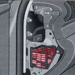 Fuse box location
The Audi A4 B5 fuse box is located on the left side of the dashboard (see image on the right).
To admission information technology you must have the left paw side door open and remove the side dash cover, pushing it.
Fuxe box diagram and amperage listing
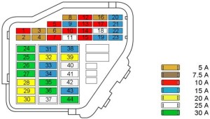 Check fuses position on the image
Fuse number – Clarification – Fuse Amperage
ane – Heated washer jets – 5A
2 – Turn signals flasher unit – 10A
3 – Headlight washer, illumination of glove compartment, engine compartment, climate control, automatic transmission, musical instrument cluster – 5A
4 – License plate light – 5A
5 – Instrument cluster, seat heating, examination connection for cruise command, bulb monitor for auto-check control, Automated transmission display, switch lighting, mirror switches and actuators, airbag warning light, exterior temperature indicator, Climate control – 10A
6 – Central locking system – 5A
7 – Anti-lock brake arrangement – 10A
8 – Empty
9 – Mirror heating – 10A
10 – Empty
11 – Cruise command (automatic transmission) – 5A
12 – On board diagnostic arrangement – 10A
13 – Brake lights – 10A
fourteen – Interior lights, reading lights, anti-theft alarm system, vanity mirror – 10A
15 – Musical instrument cluster, power windows, climate control, automatic transmission – 10A
16 – Anti-lock brake organisation, Anti-Slip-Regulation – 5A
17 – Heated door locks – 10A
18 – High beam right – 10A
19 – High beam left – 10A
xx – Low beam right – 15A
21 – Low beam left – 15A
22 – Tail and side marking right – 5A
23 – Tail and side marker left – 5A
24 – Wiper and washer system – 25A
25 – Blower for heating, climate control – 30A
26 – Rear window defogger, mirror heating – 30A
27 – Rear window wiper – 15A
28 – Fuel pump – 15A
29 – Engine timing – 20A
30 – Sun roof – 20A
31 – Tail lights, cruise command, automatic transmission – 15A
32 – Engine timing – 20A
33 – Cigarette lighter – 15A
34 – Engine timing – 15A
35 – Trailer receptacle – 30A
36 – Fog lights – 15A
37 – Radio – 20A
38 – Luggage compartment light, central locking system – 15A
39 – Emergency flasher – 15A
40 – Horn – 25A
41 – Anti-lock brake system – 25A
42 – Empty
43 – Empty
44 – Seat heating – 30A
The instructions in this tutorial will piece of work in the following model years:
1994, 1995, 1996, 1997, 1998, 1999, 2000 and 2001 Audi A4 B5 Petrol (1.6, ane.eight, 1.8T, 2.iv v6, two.8 v6) and Diesel fuel (1.nine TDI and 2.5 TDI) Engines, S4 and RS4
How to find Audi engine code
March ii, 2016 in Audi A3 8L (1996 to 2003), Audi A4 B5 (1994 to 2001), Audi A4 B6 (2000 to 2006), Audi A6 C5 (1997 to 2005), Audi A6 C5 Allroad Quattro (1999 to 2005), Audi A8 D2 (1994 to 2002), Audi A8 D3 (2002 to 2010), Audi TT 8N (1998 to 2006), Generic How To'south by admin
When y'all are searching for something to your cas, sometimes information technology'due south usefull to know what is the code of the engine.
You have 2 options to easily retrieve the engine code of your car:
1. Wait in your service book. On the first you'll have a blackness and white sticker.
2. Expect in your spare tyre well, and you'll find the same blackness and white sticker.
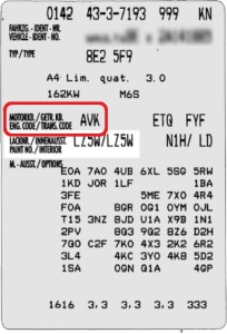
This sticker have severall information regarding your car (engine code, gearbox lawmaking, paint code, trim code and all the choice codes).
The engine code is the commencement information on the 4th line (highlighted in cerise in the paradigm on the left).
Audi A4 B5 Torque Specs (1994 to 2001)
April 23, 2015 in Audi A4, Audi A4 B5 (1994 to 2001) by admin
Listing of Audi A4 B5 (1994 to 2001) FWD and AWD (Quattro) bolts and basics tightening torque specifications.
Cautions:
– Screws coated with locking fluid or sealant must always be replaced with new screws during reinstallation.
– Screws coated with a locking fluid or self locking nuts must exist replaced with new when reinstalled.
– E'er use new screws and nuts when angle tightening. Whatsoever exceptions to this rule will be indicated in the method.
– Just nuts and screws which are not self locking tin be reused provided that they are in proficient condition.
FRONT Clench Bolts – Anti Gyre/Stabilizer Bar To Subframe (Hexagon Bolt) :
18 Ft-Lbs \ 216 In-Lbs \ 24.four N-m
REAR – AWD – Bushing Clamp Bolts – Anti Roll/Stabilizer Bar To Subframe (Bolt – Nut) :
xviii Ft-Lbs \ 216 In-Lbs \ 24.4 N-k
REAR – 2WD – Pivot Bolts :Axle Beam To Mount (Bolt – Nut) :
59 Ft-Lbs \ 708 In-Lbs \ 79.99 Due north-thou + 90deg
FRONT LOWER Ball Articulation Nut :Ball Joint To Steering Knuckle (Nut) :
74 Ft-Lbs \ 888 In-Lbs \ 100.33 Due north-yard
FRONT UPPER Ball Joint Clench Nut & Bolt :Ball Joint To Steering Knuckle (Commodities – Nut) :
30 Ft-Lbs \ 360 In-Lbs \ 40.67 Due north-m
AWD – Bulldoze Shaft Bearing Bracket Nuts :Subclass/Stay To Floor Pan (Nut) :
eighteen Ft-Lbs \ 216 In-Lbs \ 24.iv Due north-k
Front end Guide Pins – Lucas :Caliper To Caliper Mounting Bracket :
22 Ft-Lbs \ 264 In-Lbs \ 29.83 N-m
Forepart Guide Pins – Teves/Ate :Caliper To Caliper Mounting Bracket :
18 Ft-Lbs \ 216 In-Lbs \ 24.iv N-m
REAR Guide Pins :Caliper To Caliper Mounting Bracket :
26 Ft-Lbs \ 312 In-Lbs \ 35.25 N-m
Forepart :Caliper Mounting Bracket To Steering Knuckle (Hexagon Bolt) :
92 Ft-Lbs \ 1104 In-Lbs \ 124.74 North-thousand
REAR :Caliper Mounting Bracket To Rear Knuckle (Hexagon Bolt) :
seventy Ft-Lbs \ 840 In-Lbs \ 94.91 N-m
Clutch Principal Cylinder To Firewall (Allen Bolt) :
15 Ft-Lbs \ 180 In-Lbs \ 20.34 N-k
Clutch Release Cylinder To Transaxle (Hexagon Commodities) :
18 Ft-Lbs \ 216 In-Lbs \ 24.four N-m
FRONT (Front Arm Pivot) :Control Arm-Lower To Subframe (Bolt – Nut) :
59 Ft-Lbs \ 708 In-Lbs \ 79.99 N-m + 90deg
Front end (Rear Arm Pivot) :Control Arm-Lower To Subframe (Bolt – Nut) :
66 Ft-Lbs \ 792 In-Lbs \ 89.48 N-m + 90deg
REAR LOWER – AWD – NOTE :52 FtLbs :Control Arm-Lower To Subframe (Bolt – Nut) :
52 Ft-Lbs \ 624 In-Lbs \ lxx.5 Northward-one thousand + 90deg
REAR LOWER – AWD :Control Arm-Lower To Rear Knuckle (Bolt – Nut) :
70 Ft-Lbs \ 840 In-Lbs \ 94.91 Due north-g
REAR – AWD – Pin Bolts :Command Arm-Upper To Subframe (Commodities – Nut) :
37 Ft-Lbs \ 444 In-Lbs \ 50.17 N-m + 90deg
FRONT Pivot Bolt :Control Arm-Upper To Mount (Commodities – Nut) :
xxx Ft-Lbs \ 360 In-Lbs \ twoscore.67 N-thou + 90deg
REAR – AWD :Control Arm-Upper To Rear Knuckle (Commodities – Nut) :
37 Ft-Lbs \ 444 In-Lbs \ 50.17 N-g + 90deg
REAR – 2WD :Damper Mounting Plate To Trunk (Hexagon Bolt) :
18 Ft-Lbs \ 216 In-Lbs \ 24.4 North-g
FRONT LOWER to Lower Command :Damper/Shock Absorber To Control Arm-Lower (Bolt – Nut) :
66 Ft-Lbs \ 792 In-Lbs \ 89.48 N-grand
REAR – AWD :Damper/Stupor Absorber To Control Arm-Lower (Bolt – Nut) :
52 Ft-Lbs \ 624 In-Lbs \ lxx.5 Northward-m + 90deg
REAR LOWER – 2WD :Damper/Daze Absorber To Trailing Arm (Bolt – Nut) :
37 Ft-Lbs \ 444 In-Lbs \ 50.17 Due north-g + 90deg
FRONT Damper Shaft Nut :Damper/Stupor Cushion To Damper Mounting Plate (Nut) :
44 Ft-Lbs \ 528 In-Lbs \ 59.66 N-grand
Front UPPER to Command Arm Mounting Bracket :Damper/Daze Absorber To Mount (Nut) :
15 Ft-Lbs \ 180 In-Lbs \ 20.34 Due north-g
REAR – AWD – UPPER :Damper/Shock Absorber To Mount (Commodities – Nut) :
52 Ft-Lbs \ 624 In-Lbs \ 70.five N-thousand + 90deg
REAR UPPER – 2WD – Damper Shaft Nut :Damper/Shock Absorber To Mount (Nut) :
18 Ft-Lbs \ 216 In-Lbs \ 24.iv Due north-m
AWD – Forepart Cantankerous Member :Differental Assembly To Differential Crossmember (Hexagon Commodities) :
30 Ft-Lbs \ 360 In-Lbs \ 40.67 N-m
AWD – Rear Cross Member :Differental Assembly To Differential Crossmember (Hexagon Bolt) :
41 Ft-Lbs \ 492 In-Lbs \ 55.59 North-yard
REAR – AWD :Differential Crossmember To Trunk – 8mm bolts (Grand 8 X 1.25 Hexagon Bolt) :
17 Ft-Lbs \ 204 In-Lbs \ 23.05 Northward-m
REAR – AWD :Differential Crossmember To Trunk – 10mm bolts (1000 10 X 1.50 Hexagon Commodities) :
30 Ft-Lbs \ 360 In-Lbs \ 40.67 N-grand
MANUAL Transaxle Drain Plug :Drain Plug To Transaxle (Hexagon Bolt) :
26 Ft-Lbs \ 312 In-Lbs \ 35.25 Due north-yard
REAR Inner CV Joint :Drive Beam To Differental Assembly (M 8 X 1.25 Allen Bolt) :
30 Ft-Lbs \ 360 In-Lbs \ 40.67 North-m
FRONT Inner CV Joint – Brawl & Cage :Bulldoze Beam To Transaxle (K 10 Ten i.50 Allen Bolt) :
59 Ft-Lbs \ 708 In-Lbs \ 79.99 N-thousand
Front end Inner CV Joint – Ball & Muzzle :Drive Axle To Transaxle (G 8 X one.25 Allen Commodities) :
thirty Ft-Lbs \ 360 In-Lbs \ twoscore.67 North-m
Front Inner CV Joint – Triple Rotor :Drive Axle To Transaxle (Chiliad 10 X 1.50 Allen Commodities) :
59 Ft-Lbs \ 708 In-Lbs \ 79.99 N-m
AWD Drive Shaft CV Articulation Bolts :Bulldoze Shaft To Differental Assembly (Hexagon Bolt) :
41 Ft-Lbs \ 492 In-Lbs \ 55.59 N-thou
AWD Drive Shaft CV Articulation Bolts :Drive Shaft To Transfer Case Associates (Hexagon Bolt) :
41 Ft-Lbs \ 492 In-Lbs \ 55.59 North-m
Front end :Driblet Link To Command Arm-Lower (Nut) :
30 Ft-Lbs \ 360 In-Lbs \ twoscore.67 Northward-m
Front end Brawl Articulation :Drop Link To Anti Roll/Stabilizer Bar (Nut) :
74 Ft-Lbs \ 888 In-Lbs \ 100.33 Due north-m
FRONT Bushing :Drop Link To Anti Curl/Stabilizer Bar (Nut) :
30 Ft-Lbs \ 360 In-Lbs \ 40.67 North-k + 90deg
REAR – AWD :Drop Link To Anti Roll/Stabilizer Bar (Bolt – Nut) :
37 Ft-Lbs \ 444 In-Lbs \ l.17 North-m
REAR – AWD :Driblet Link To Rear Knuckle (Bolt – Nut) :
37 Ft-Lbs \ 444 In-Lbs \ 50.17 N-m
Manual Transaxle Make full Plug (Hexagon Commodities) :
18 Ft-Lbs \ 216 In-Lbs \ 24.4 N-k
Hub To Bulldoze Axle (14mm Hexagon Commodities) :
85 Ft-Lbs \ 1020 In-Lbs \ 115.24 North-chiliad + 180deg
Hub To Drive Axle (16mm Hexagon Commodities) :
140 Ft-Lbs \ 1680 In-Lbs \ 189.81 North-m + 180deg
Automatic Transaxle Mount :Mount To Transaxle :
thirty Ft-Lbs \ 360 In-Lbs \ 40.67 North-thou
Automatic Transaxle Mount :Mountain To Subframe :
17 Ft-Lbs \ 204 In-Lbs \ 23.05 N-m
Forepart Upper Control Arm Mountain to Torso :Mount To Body (Hexagon Commodities) :
55 Ft-Lbs \ 660 In-Lbs \ 74.57 N-thousand
REAR – 2WD – Axle Mount :Mount To Body (Hexagon Bolt) :
55 Ft-Lbs \ 660 In-Lbs \ 74.57 Due north-m
REAR – AWD – UPPER Control Arm/Damper Mount :Mount To Torso (Hexagon Commodities) :
41 Ft-Lbs \ 492 In-Lbs \ 55.59 North-m
AUTOMATIC Transaxle Mount Centre Boly – Mount To Mount (Bolt – Nut) :
30 Ft-Lbs \ 360 In-Lbs \ xl.67 N-chiliad
Power Brake Booster To Firewall (Hexagon Bolt) :
eighteen Ft-Lbs \ 216 In-Lbs \ 24.4 N-grand
Power Steering Hose To Steering Gear – Pressure Line – Hollow Commodities (Banjo) (Hexagon Bolt) :
30 Ft-Lbs \ 360 In-Lbs \ 40.67 N-m
Ability Steering Hose To Steering Gear – Return Line – Hollow Bolt (Banjo) (Hexagon Commodities) :
37 Ft-Lbs \ 444 In-Lbs \ 50.17 N-grand
REAR – AWD – Lower Dorsum Runway Rod :Radius/Track Arm To Subframe (Bolt – Nut) :
66 Ft-Lbs \ 792 In-Lbs \ 89.48 Northward-m
REAR – AWD – Lower Back Track Rod :Radius/Rails Arm To Rear Knuckle (Bolt – Nut) :
37 Ft-Lbs \ 444 In-Lbs \ l.17 N-m
REAR – 2WD – Stub Axle :Spindle To Trailing Arm (Hexagon Commodities) :
22 Ft-Lbs \ 264 In-Lbs \ 29.83 N-chiliad
Steering Gear To Subframe (Hexagon Commodities) :
48 Ft-Lbs \ 576 In-Lbs \ 65.08 N-m
Subframe To Body Mounting Bolts (Hexagon Commodities) :
81 Ft-Lbs \ 972 In-Lbs \ 109.82 N-grand + 90deg
Necktie Rod End To Steering Knuckle Clamp Nut & Bolt (Commodities – Nut) :
33 Ft-Lbs \ 396 In-Lbs \ 44.74 Northward-one thousand
Tie Rod Terminate To Steering Knuckle Vertical Commodities (Hexagon Bolt) :
5 Ft-Lbs \ threescore In-Lbs \ 6.78 N-m
AWD :Torque Tube To Differental Assembly (Hexagon Bolt) :
26 Ft-Lbs \ 312 In-Lbs \ 35.25 N-g
Transaxle To Engine Block (Chiliad 10 Ten 1.fifty Hexagon Bolt) :
33 Ft-Lbs \ 396 In-Lbs \ 44.74 N-m
Transaxle To Engine Block (M 12 X ane.l Hexagon Bolt) :
48 Ft-Lbs \ 576 In-Lbs \ 65.08 N-m
How To Reset OIL or INSP message in Audi A4 B5 (1994 to 2001)
January 6, 2015 in Audi A4, Audi A4 B5 (1994 to 2001), Service Indicator Reset by admin

For reset the OIL message that appears in your Audi A4 B5 nuance panel odometer screen, follow the instructions:
For 1994 to 1999 cars:
Stride 1. Insert your key into the ignition (do not plow it)
Step ii. Button in the odometer reset button (right push button), hold it pressed, and turn the fundamental to the offset click.
Stride iii. In the display, "oil" or "service" or "insp" should now be shown. If it does not, repeat steps 1. and two.
Stride 4. To reset, pull out your instrument light dimmer button at the bottom of the tachometer. (—— are now displayed)
Stride five. Turn the ignition to the off position. When the ignition is turned dorsum on, the display should be dorsum to the trip odometer.
For 2000 to 2001 cars:
Stride 1. Insert your key into the ignition (practise not turn information technology)
Step 2. Button in the odometer reset push button (right button), hold it pressed, and turn the central to the first click.
Step 3. In the brandish, "oil" or "service" or "insp" should now be shown. If it does not, echo steps i. and 2.
Step 4. To reset, push the clock aligning knob the bottom of the tachometer.(—— are now displayed)
Stride 5. Plow the ignition to the off position. When the ignition is turned back on, the display should be back to the trip odometer.
The instructions in this tutorial will work in the following model years:
1994, 1995, 1996, 1997, 1998, 1999, 2000 and 2001 Audi A4 B5 Petrol (1.half dozen, 1.viii, 1.8T, ii.4 v6, 2.eight v6) and Diesel (one.9 TDI and ii.5 TDI) Engines, S4 and RS4
This website uses cookies to improve your experience. Nosotros'll presume you're ok with this, only you tin can opt-out if you wish.Accept Read More
DOWNLOAD HERE
+aeb Vacuum Diagram Audi A4 B5 1.8t
Posted by: barthbobst1962.blogspot.com
0 Response to "+aeb Vacuum Diagram Audi A4 B5 1.8t"
Post a Comment